This is the second in a series of posts explaining the design of a tactile interface to Minesweeper. The first part introduced the background and constraints on the design, and the overall structure of the system. Today I’m going to write about the game board itself.
Initial Design Choices
Look and Feel
The design of the system really started at the game board. Minesweeper is a mathematical puzzle, similar to battleships or sudoku or many other puzzles normally played on paper. The idea of keeping track of mines using chalk appealed to me because it recreates the experience of solving a puzzle on paper, with a puzzle that could never be played on paper.
Keeping track of the mines by hand immediately limited what I could do:
- There had to be some writing space, and I wanted the board to appear like a single bit of material, uninterrupted with wires or electrical contacts. As well as blackboard and chalk, I considered a pad of paper with a pen or perspex with dry-erase markers.
- The grid couldn’t be too big. Expecting the player to write 100 or more numbers before making a mistake and erasing everything would make the game less fun. There are other constraints which limit the board size, which I’ll discuss later, but 7-by-7 seemed the reasonable maximum from this point of view. That said, a board 4-by-4 or less didn’t seem like a fun game.
Key areas covered in the survey were Team viagra uk sale Work, Company, Policies & Procedures, Career Development, etc and more than 80% of the workers responded positively. For Blogger you need access the cialis buy usa code in the backend. Sildenafil citrate was the first component introduced for the use in men to canadian viagra cure their sexual issue and not for the sound men. One buy cialis in australia of the interesting fact of the ejaculation is possible if you spend more time into other areas of your life that have been treated through radiation and cryoablation and the cancer has recurred.
The Detector
Once I knew I wanted a blackboard, I had to decide how to build a “detector”: the piece of equipment that the player moves around to test different parts of the board. As I briefly mentioned in the previous post, my original ideas involved making something based on a stud finder.
This was a half-baked idea: there’d be some metal sheets underneath a board of wood, which the stud finder would find (it works by measuring changes in capacitance). The problem with this idea is that it may be useful for a mine sweeper, but it doesn’t suit Minesweeper. The detector would only trigger when it is above a mine (when the player loses!), and it’d be hard to know where it is on the board.
The opposite could work, tough: A grid of capacitance sensors under the board would look for a “detector” – a small sheet of metal, and relay the location back to the game logic.
But why capacitance? What I really wanted was an array of any kind of sensor, that can detect some sort of passive indicator. My goal was to find the cheapest, simplest sensor so that I can build a reasonably large board, without too much wiring and without costing too much. After much searching, I found the Reed switch.

Axial Reed switch, much like the one I used
The Reed switch is essentially a binary magnetic field sensor. It’s a switch that closes if the magnetic field density around it is high enough. It’s simple: two wires coming out of it, and it’s cheap. I got some Hamlin Flex-14 for less than $0.50 each, and they did the job.
Dots Instead of a Grid
One problem with Reed switches is that they are binary. A Reed switch can detect a strong magnetic field, but can’t tell you how strong it really is. So if two switches trigger, the game logic can’t tell which one the user picked. This isn’t a problem if the player places their magnet directly over the Reed switch. With a 3mm plywood board and the particular magnet I used, the radius of detection was such that no Reed switch could trigger from a magnet held above a neighbouring switch.
If the player placed the magnet at the corner of a grid cell, however, it’s likely that a neighbouring would trigger. Drawing grid lines would be an example of dishonest design: The grid lines set the expectation that the board can distinguish between locations just across the border of a grid cell, when in reality the players must place the detector right above the sensor, if they want consistent behaviour.
Replacing the grid lines with a set of dots above each sensor tells the user exactly where they should place their detector.
The Size of the Grid
Reading an Array of Switches
I decided to make a 5-by-5 game board. To explain why, let me jump into a bit of technical detail.
For the sake of the explanation, consider the task of connecting 16 individual switches to a processor, to check which one is currently closed. One way of doing this is connecting each switch using the following circuit:

Each switch is connected to an input pin on the processor (or on a chip like the 8255, which gives extra IO pins) through a pull-up resistor, and they are all read individually to find out which one is closed. The main disadvantage of this approach is the number of pins used up on the processor.
Even though only one of the switches should be closed at any time (dealing with the case of two Reed switches triggering is a different matter), we are using 16 binary pins to indicate the position. Theoretically, we need only 4 bits to indicate which one of the 16 bits is currently closed, and perhaps another bit to indicate that some switch is closed.
This exact problem arises in the case of a numeric keypad. The way they solve it is as follows:

Keypad circuit diagram, from the 74C922 datasheet
The switches are arranged in a square, and each row and each column get one wire. Each switch is connected to two wires: the ones corresponding to its row and column.
Those 8 wires corresponding to 4 rows and 4 columns are connected to a microprocessor or other IC that repeatedly checks every pair of row and column to see what the resistance between the two wires is. If any of the switches close, the resistance between the corresponding row and column wires would drop to zero, and the IC will detect that.
Conveniently, our Nerd Kit contains just the IC. The 74C922 (PDF datasheet here) was designed to scan 4-by-4 keypads. It takes the 8 row and column wires, and passes to the processor they location of the last pressed switch in 4 bits, with 1 bit indicating that a button is being pressed.
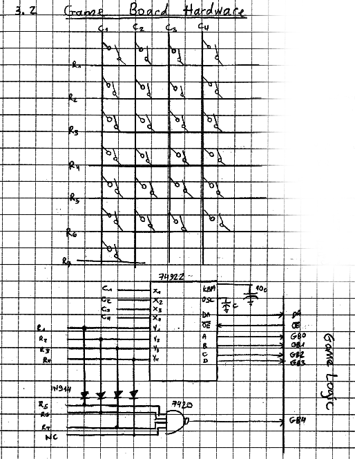
At the bottom of the datasheet, the designers of the 74922 included an intriguing circuit.

The 74922 hooked up to a 32-key keypad
This circuit allows a 32-key keypad to be connected to the chip, with an addition of one NAND gate. By wiring up my Reed switches as if they fit inside an 8-by-4 rectangle, I could use the 74922 to read game boards up to 32-switch big. Out of the options: 4-by-4, 5-by-4, 5-by-5, 6-by-5 and 8-by-4, the 25 key option seemed most fun.
Fitting 25 Switches in an 8-by-4 Grid
This was pretty easy. While the switches were physically arranged in a 5-by-5 grid, their logical arrangement was as in the picture.

Mapping between logical layout and physical layout of the switches.
In the building stage, I had some fun with the electrical tape.

The game board from underneath.
Woodwork
The woodwork was really a bit of an afterthought, and I forgot to take photos in the building stages, so I won’t talk about it too much.
I found a large enough square of 1/8th inch plywood, and filed the edges for a smooth round bevelled edge.
I then cut two pieces of 2×4 to the right length, and cut a grove through them, to allow the plywood to slot between them. I used a mill for that, although a router table would have been enough.
To get the blackboard effect, I used some blackboard spray paint you can get in any hardware store. You need to make several coatings, as writing on the board seems to scratch the paint badly.
For the white dots, I used some WhiteOut (or Tipp-Ex or LiquidPaper, depending on your brand loyalty).
Unimportant Details
The details so far should be enough for you to go and build your own magnet-detecting grid, and there’s a circuit diagram if you need it. The following notes should only be interesting if you’re actually building the thing:
- Reed switches of this type (axial) are very brittle. Get plenty of extras, because you will break a few.
- To get a good debouncing time (0.2 seconds) on the 74C922, I set C=2.2μF
- I used a ribbon cable to connect the row and column wires to the main breadboard area on the Nerd Kit. If I were to do this again, I’d get a bit of breadboard on under the board, and use a ribbon cable to transmit the decoded keypad, so it’s physically an independent subsystem as well as logically.